As electronic products increasingly demand miniaturization, high integration, and stringent cost control, traditional ceramic substrates are being replaced by Printed Circuit Boards (PCBs) due to their high cost. In this transition, embedded resistor technology, which integrates resistive elements within the PCB, becomes crucial.
As a professional pcb maker, AUSPI team try to explore Carbon Ink Resistorsas a low-cost, easily implemented alternative for PCB embedded resistors.
We will conduct an in-depth comparison with traditional thin/thick film embedded resistor technologies (e.g., OhmegaPly), covering technical principles, material characteristics, pros and cons, and industry applications, to provide a reference for engineers selecting the appropriate embedded resistor solution in cost-sensitive applications.
Technical Principles and Process
Embedded resistor technology aims to move resistive elements from the Surface Mount Technology (SMT) layer to the inner layers or surface of the PCB, saving space, shortening signal paths, and improving high-frequency performance. Key embedded resistor technologies include thin-film technology based on resistive foil and thick-film technology based on conductive paste.
1.1 Carbon Ink Resistor
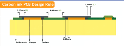
Carbon ink resistors utilize the screen printing process to precisely print conductive carbon ink, composed of carbon powder, resin, and solvent, onto the copper foil or insulating layer of the PCB substrate (typically FR4). After high-temperature curing, the ink forms a carbon film with a specific resistance value. The resistance value is primarily determined by controlling the ink’s formulation, printing thickness, and the length and width of the resistive body. This process is similar to legend printing in PCB manufacturing, offering extremely high cost-effectiveness and process compatibility.
1.2 Traditional Embedded Resistor Technology
Traditional embedded resistor technologies, such as OhmegaPly (resistive foil) and TCR (thick film resistor), typically employ more precise processes:
- Resistive Foil (e.g., OhmegaPly):
A resistive material, such as a Nickel-Phosphorus (NiP) alloy, is pre-plated onto standard copper foil. During PCB manufacturing, the resistor body’s shape and size are precisely defined using photolithography and etching processes, similar to creating standard copper traces.
- Thick Film Paste (e.g., TCR):
Special conductive pastes (often containing precious metal oxides) are applied to inner layers via printing or sputtering, and then laser trimmed to achieve higher precision.
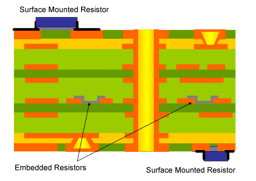
Figure 1, illustrates the structural difference between carbon ink resistors and traditional embedded resistors in a PCB cross-section.
Material Characteristics and Performance Comparison
The user’s shift from expensive ceramic substrates to PCBs is primarily driven by cost reduction. Carbon ink resistors offer a significant cost advantage, but they show a clear gap in critical electrical performance parameters compared to traditional embedded resistors and high-precision SMT resistors.
2.1 Comparison of Key Parameters
The table below compares the differences in key performance indicators between carbon ink resistors and traditional embedded resistor technologies [1] [2] [3].
| Characteristic | Carbon Ink Resistor | Traditional Embedded Resistor – e.g., OhmegaPly | SMT Resistor |
| Process Cost | Much Lower | Higher | Low |
| Tolerance | Low, ±10% ~ ±30% | High, Standard ±15%, Advanced up to ±3% | Higher, up to ±0.1% |
| TCR | High, > ±200 ppm/°C | Low, typically < ±100 ppm/°C | Lower, up to ±5 ppm/°C |
| Sheet Resistivity | 50 ~ 200 Ω/□ | 10 ~ 100 Ω/□ | N/A |
| Stability | Good, but highly dependent on printing and curing process | Excellent, High reliability | Excellent |
| Advantage | Cost and Process Simplicity | Precision and Stability | Precision and Flexibility |
2.2 Performance Analysis
Cost and Process:
The biggest advantage of carbon ink resistors is cost. They utilize existing PCB screen printing equipment, eliminating the need for expensive special laminates or complex etching processes, making them the most economical way to implement embedded resistors on a PCB.
Tolerance and TCR:
The precision and temperature stability of carbon ink resistors are their main limitations. A tolerance of ±10% to ±30% means they can only be used in low-precision applications such as voltage dividers, current limiters, or pull-up/pull-down circuits. In contrast, traditional embedded resistors (e.g., OhmegaPly) achieve higher precision and lower TCR through photolithography and etching, making them suitable for circuits sensitive to temperature drift.
Consideration for Ceramic Substrate Replacement:
Ceramic substrates are often used in high-power, high-frequency, or applications requiring extreme thermal stability. If the resistors on the original ceramic substrate are high-precision or high-power, the carbon ink resistor may not be a direct replacement, as its precision and heat dissipation capabilities are inferior to thick-film resistors on ceramic substrates or traditional embedded resistors. The user must carefully evaluate the application’s requirements for resistor precision.
Pros, Cons, and Application Scenarios
3.1 Pros and Cons of Carbon Ink Resistors
| Advantages | Disadvantages |
| Extremely Low cost: Lowest material and process cost solution. | Low Precision: Loose tolerance, high TCR, unsuitable for precision circuits. |
| Simplify Process: be Compatible with standard PCB screen printing process. | Resistance Range Limit: Resistance limited by ink formulation and printing dimensions. |
| Space Saving: Integrates resistor function into PCB, saving SMT space. | Reliability Challenges: Resistance highly affected by printing thickness, curing temperature, etc.. |
| Versatility: It can be used for keypad contacts, jumper wires, low-precision resistors. | Heatsink Capacity: Inferior heat dissipation compared to ceramic substrates or high-power SMT resistors. |
3.2 Industry Applications
| Technology | Industrial Applications | Suitability for Ceramic Substrate Replacement |
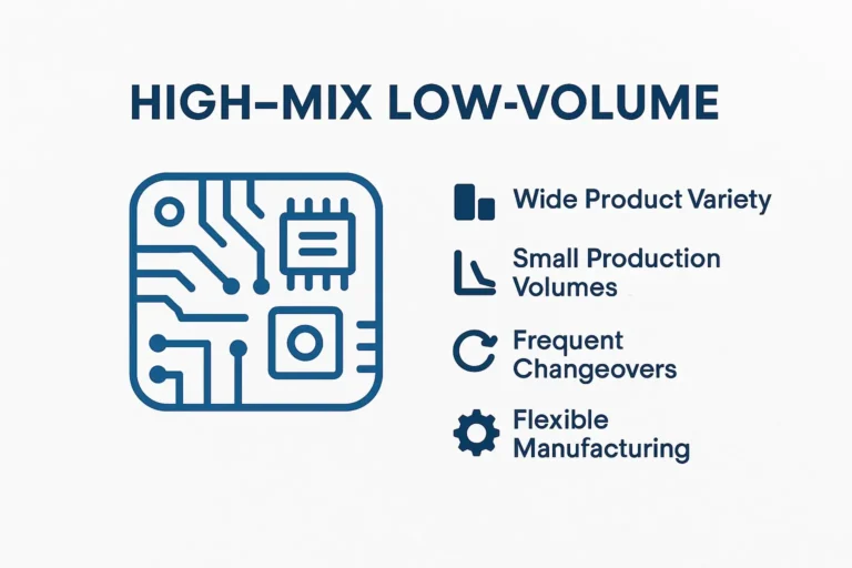
| Carbon Ink Resistor | Consumer Electronics: Conductive contacts for keypads such as remote control, keyboard or Game controller; Cost effective power management voltage division or current limit, LED driver. | Suitable for low-cost, high-volume applications with low precision and TCR requirements. |
| Traditional Embedded Resistor | High-Speed Communication: Impedance matching, termination resistors; Military/Medical: High-reliability power and signal processing; RF/Microwave: Parasitic-sensitive circuits. | Suitable for applications requiring high precision, high stability, and improved high-frequency (HF) performance. |
AUSPI Recommendations for Designers
The user’s decision to switch from ceramic substrates to PCBs and consider carbon ink resistors is a reasonable choice driven by cost. Carbon ink resistors offer the most cost-effective way to integrate resistive functions onto a standard FR4 PCB, especially suitable for replacing low-precision resistive elements on ceramic substrates.
Evaluate Precision Requirements:
Carefully check the tolerance and TCR requirements of the resistors in the original ceramic substrate design. If the requirement is higher than ±10% or the TCR is lower than ±200 ppm/°C, carbon ink resistors may not be suitable, and traditional thin-film embedded resistor technology or high-precision SMT resistors should be considered.
Optimize Design:
The resistance accuracy of carbon ink resistors is highly correlated with printing dimensions and process stability. The design should use large-sized, high aspect ratio resistive elements to improve accuracy, and close cooperation with the PCB manufacturer is necessary to ensure resistance consistency through process control and in-line testing.
Avoid Critical Circuits:
Avoid using carbon ink resistors in critical circuits such as voltage references, precision sampling, or high-frequency terminations. Limit their use to functions like keypad contacts, up and down for low-speed signals, or simple current-limit protection.